ISO 10110 optics design norm : a complete guide
International ISO standards are use to enable designers, manufacturers and user to understand each other in a simplified way. When it comes to optical components, one norm is tremendously used in Photonics industry : the ISO 10110 standard. Optics are complex elements that are not easily defined, below you’ll find a complete guide about this norm and learn or review everything you need to know about optics design:
ISO 10110
This standard, named : “Optics and optical Instruments – Preparation of optical drawings for optical elements and systems“, used for specifying optical elements can be divided into two main parts : drawing and specifications.
Drawing layout
ISO101110 drawings are divided into 3 main parts : the drawing itself, usually on the top, three columns corresponding from left to right to left side specifications, material specifications and right side specifications, and at the bottom the usual general information about the drawing.
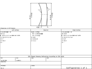
ISO 10110 drawing example
Sketch drawing
It enable a global view of the part and sometimes zoom in specific areas. Shows the symmetry axis, polished surfaces, mechanical dimensions and other informations.
Optical details
On the three columns, the central one is used to detail raw material, including raw material name and its basic characteristics (Nd, Vd) and material imperfections as details in points 2 to 4 in next paragraph.
On the right and left column, first lines are to define the shape of the surface :
- CC : for concave
- CX : for convex
- ∞ : for flat surface
- R for radius of curvature value or equation if the surface is aspherical.
- Øe : for effective surface diameter
Then comes the surface treatment and surface aspect specifications as detailed in point 5 to 13 in below paragraph.
The 13 specifications types
The standard refers to 13 points to detail information about the optical elements. The 13 can be specified or left empty on the drawing if irrelevant or not important, some of them are represented by a number or a token.
1. General remarks
Mostly mechanical specifications, by default metric system is used with dimension in millimeter unless otherwise specified.
First angle projection is used for the drawing views.
2. Material stress birefringence
Appears in the form of “0/X” where “X” will be the max allowed birefringence in mm/cm.
3.Material bubbles and inclusions
This specification is detailed as 1/N*A, with N an integer relating the maximum allowed number of bubbles or inclusion fitting in a A*A square (in mm).
4. Material inhomogeneity and striae
Referred with a 2/A;B where A refer to a specific class for refractive index inhomogeneity and B a class of striae.
| A Class | Max variation of refractive index |
|---|---|
| 0 | 50*10^-6 |
| 1 | 20*10^-6 |
| 2 | 5*10^-6 |
| 3 | 2*10^-6 |
| 4 | 1*10^-6 |
| 5 | 0,5*10^-6 |
| B Class | Density of Striae causing an optical path difference of at least 30nm |
|---|---|
| 1 | 10% |
| 2 | 5% |
| 3 | 2% |
| 4 | 1% |
| 5 | Extremely low amount of striae, specification to be clarified by written |
5. Surface form tolerance
Specification of the optical surface form, written in a 3/A(B/C) format.
- A is the maximum spherical sag error, can be left empty if specified on the drawing.
- B is the peak to valley maximum value (PV)
- C is the maximum rotational symmetric PV figure error or best fit aspheric surface.
Values are in fringe.
6. Centering tolerance
Specification of centering of the optical element appears as 4/α, where α stands for the maximum angle value between the measured surface and the reference surface.
7. Surface imperfection tolerance
Imperfection tolerance are written with the callout 5/N*A, with N the integer max number of imperfections fitting in a A*A square (in mm).
8.Surface texture
Use the different surface texture symbols with some letter references :
- G : ground
- Rq : RMS roughness in µm
- L : sampling length
- P & PM : polished surfaces
- PSD : Power Spectral Density
9 : Surface treatment and coating
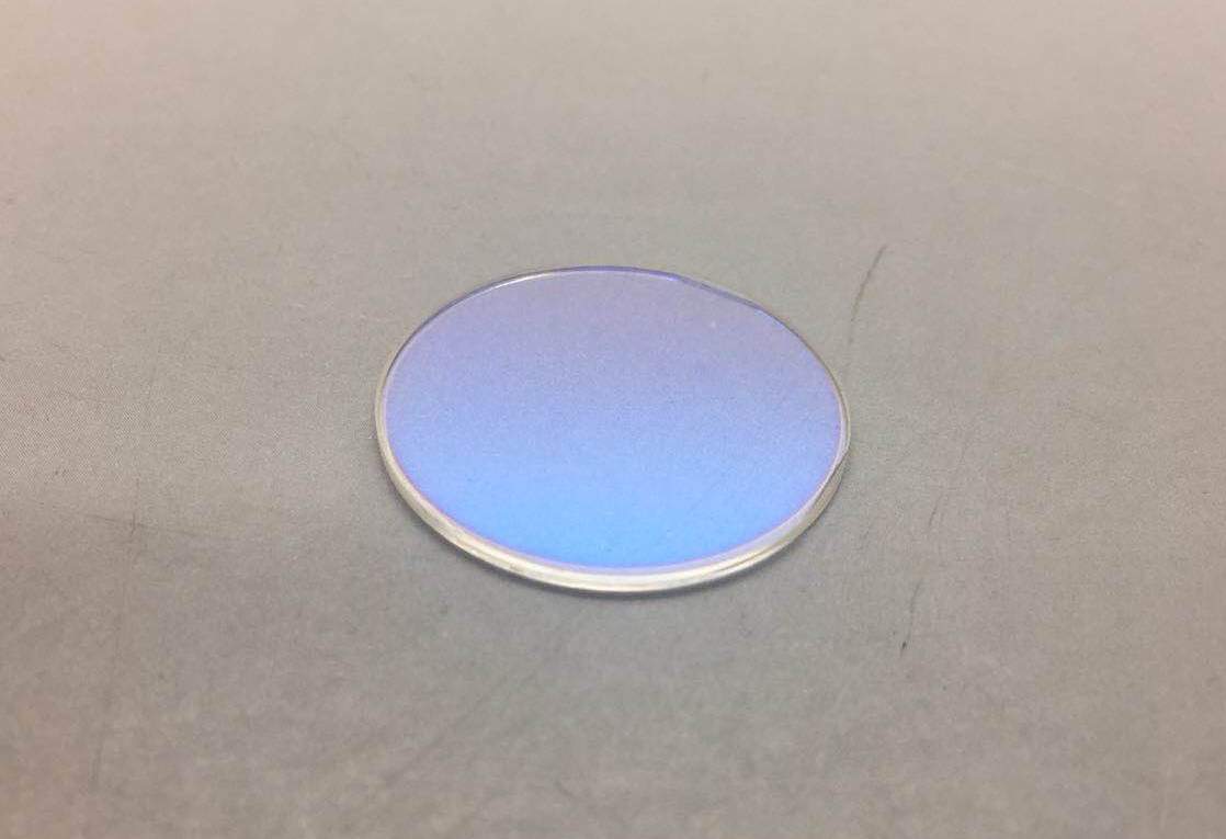
The symbol for surface treatment is a λ in a circle followed by reference and/or specifications of the treatment. For examples AR will stand for Anti-Reflect and BBAR for Broad Band Anti-Reflect.
Coating can also be a painting or gluing for a lens assembly (doublet).
10 : Table representing data of a lens element
Description of how to represent the data in a tabular form.
11 : Non toleranced data
In case specifications are not detailed below specification applies :
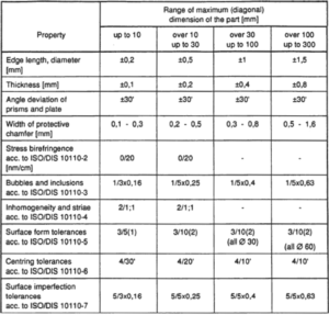
Default tolerances
12 : Aspheric surface detail
Definition of the aspherical equation to define the surface.
13 : LIDT
Laser Induced Damage Threshold, noted after a “6/” reference. Including detail about the laser : continuous or pulsed, frequency, pulse duration, number of test areas and number of pulsed applied in a area. Values are expressed in power density (W/cm2) for CW lasers and energy density (J/cm2) for pulsed laser.
How to draw a ISO 10110 drawing ?
ISO10110 drawings can be done with manually or with many different software, most common ones being :