
Optical flatness and surface figure: measurement and specification
Optical flatness describes how closely a nominally plane optical surface follows an ideal plane. Surface figure is the broader term for the departure of an optical surface from its intended form—plane, sphere, asphere or freeform. These errors affect the phase of light, so they can change a reflected or transmitted wavefront even when the optic looks perfectly smooth to the eye.
The correct objective is not the tightest possible figure specification. It is the surface accuracy needed to protect the optical function: focus, beam direction, wavefront quality, image quality, cavity performance or interferometric accuracy.
Flatness and figure specifications are often given as a “lambda” ratio (ex : λ/10) or in Fringes (1.5 Fr) as described in ISO10110.
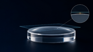
Flatness, figure, wavefront and roughness: what is the difference?
Flatness applies to a surface intended to be plane, such as an optical window, flat mirror, filter or plano face. Surface figure applies more generally to the deviation from the ideal optical prescription, including curved and freeform surfaces. On curved optics, the equivalent requirements may be described as radius, power, irregularity, form error, slope error or wavefront error.
Table with different terms concerning optical surfaces :
| Term | What it describes | Why it matters |
|---|---|---|
| Flatness | Physical departure of a nominally plane surface from an ideal plane. | Determines the reflected wavefront from that surface and partially the transmitted wavefront. |
| Surface figure | Physical departure from the requested optical form. | Controls wavefront quality, focusing and aberrations. |
| Power | Low-order deviation from a nominal surface. | Measurement of overall figure deviation to nominal shape. |
| Irregularity | Residual surface departure after specified low-order terms are removed. Also referred as waviness. | Measurement of smaller figure deviation to nominal shape. |
| Reflected wavefront error (RWE) | Compares light wavefront before and after being reflected on a surface. | At normal incidence, it is approximately twice the physical surface departure. |
| Transmitted wavefront error (TWE) | Compares light wavefront before and after passing through an optic. | Depends on both faces, thickness variation or wedge, material homogeneity and the test configuration. |
| Roughness | High-spatial-frequency surface texture. | Mainly drives scatter and stray light; it is measured over a different spatial band from figure. |
Surface figure, roughness, scratch/dig and parallelism are separate specifications. A component can have low roughness but poor flatness, or excellent flatness but insufficient scratch/dig quality. For fine-scale texture and scatter, see our companion page on optical surface roughness.
Why flatness and figure are important
The more the actual optical component is further away to its nominal shape the more the optics properties will differ from what it has been designed to.
For mirrors, light reflected wavefront will be deformed twice while it moves to the surface of the optics and comes back. For optics used in transmission light wavefront will be deformed one per surface it goes through (in and out) and also by internal material imperfections.
Coating stress, mounting stress and temperature can alter the figure of a finished component. This is particularly relevant for thin, large, lightweight or highly compliant substrates. If the assembly uses the optic after coating or in a mount, the design should consider that final state, not only the loose, uncoated substrate.
PV and RMS: two different ways of reporting figure
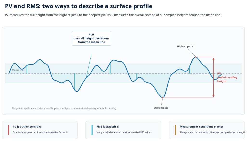
Both PV & RMS methods are used to define flatness/figure and roughness. But they are just a calculation method not a specification by themselves.
PV (peak-to-valley) is the full difference between the highest and lowest measured departure across the stated aperture. It is a worst-case metric: one isolated local high point or low point can dominate the result.
RMS (root mean square) is a statistical measure of the distribution of all sampled departures from the ideal surface after the specified processing. It often represents the general wavefront quality better than PV, but it can hide a significant isolated defect that would fail a PV requirement.
How optical flatness and figure are measured
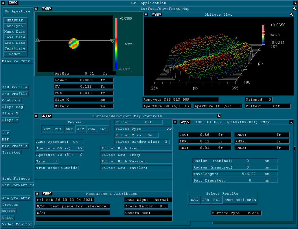
Interferometry is the principal method for demanding flatness and figure measurements. It compares a test wavefront with a calibrated reference wavefront and converts the interference pattern into a surface or wavefront map. The chosen method must match the component geometry, aperture, required accuracy and whether reflection or transmission is being tested.
Most advanced interferometers provides direct value measurements reading according to specified parameters while simpler models will show Fizeau rings which will need to be interpreted by skilled professionals.
Measuring devices are limited in aperture and shape measurement, measurement feasibility analysis should be done before production is started.
Practical remarks for a usable specification
A surface-figure specification needs a clear inspection frame. Without it, two laboratories can measure different values on the same part while both report correctly.
| Specify this item | Why it matters |
|---|---|
| Surface number and intended form | Distinguishes a plano face from a curved surface and identifies the relevant prescription. |
| Clear aperture | Figure near the edge can differ from the working aperture; limitation of measuring device should be taken into account. |
| Metric and units | State PV, RMS, power, irregularity, RWE or TWE; identify waves, fringes, nanometres or micrometres. |
| Test wavelength | A value in waves is tied to the interferometer wavelength; 632.8 nm is common but must not be assumed. |
| Removed non-critical Zernike patterns | Piston, tilt, power, astigmatism or other fitted terms can materially change PV and RMS. |
| Condition of the part | State uncoated or coated; free-standing or mounted; ambient or controlled temperature. |
| Measurement method and acceptance data | Defines the measuring instrument and the type of testing report that should be provided. |


